Showing posts with label Props. Show all posts
Wolf Medallion, The Witcher 3
Since finishing my Wolf School Swords, I’ve wanted to create more replicas from the world of the Witcher. The Wolf Medallion is an iconic part of Geralt’s gear, and a great choice for a quick project to test and improve some skills and processes. In the years that this project has been on my backlog, I had planned on using my standard fabrication process of MDF, styrene and Apoxie Sculpt, or sculpting it in modelling clay, but once I began working on it, it made sense to get it 3D printed. I started, as I often do, in Blender, challenging myself to create as high quality a digital replica of the Wolf medallion as possible, using in-game screenshots, renders from the various advertisements and high-definition movie clips, as well as photos of various pieces of merchandise as reference.


Once I was happy with the overall look of the 3D model, I printed a series of blueprints to figure out the scale, sizing off in-game reference and comparing to the hilts and pommels of my Wolf School swords. Normally, I would start fabrication at this point, but going the 3D printing route, I still had digital work to do in Blender. I took some time to figure out how I would mold and cast the piece at this stage. Realizing that the teeth could bind the cast into the mold, and that their delicate nature might lead to issues in molding and casting, I split them from the main medallion, so I could work on them separately once printed. I also made the medallion hollow, with a separate back cover, as I wanted to add some electronics. I modelled circular indents into the medallion and back cover for magnets to hold the two pieces together. With the 3D models split out, and cleaned up to avoid any issues, I had the medallion 3D printed.


The print came out pretty nicely form the Ultimaker 3, though the teeth were so small they lost most of their shape and detail. The most time-consuming part of the project was the process of priming, sanding and filling necessary to remove all the print lines and imperfections. Between the print quality and clean-up process, some of the finer detail was partially lost and had to be re-added with files and a sharp scalpel, such as the nostrils, lines along the snout and the forehead detail. The teeth were fairly rough off the print bed, and took plenty of filing and sanding to achieve their sharp, pointed look.
With everything given a final undercoat, I moved on to molding, making a 2-part block mold for each part, using Smooth-On’s Mold Max 40 as usual. I paid special attention to the vents when making the molds, placing them carefully at every point, particularly for the teeth, which were so small that the resin would not flow down into them without the assistance of venting. The finished molds were dusted with aluminium powder and cold cast using Smooth-Cast 300. The tongue presented an issue, since it trapped air bubbles, and it was in a place where I couldn’t cut a vent. After a few tests, I solved this by pouring some resin into the tongue with the mold open, then quickly sealing it and pouring the rest of the resin.

After casting enough parts for 2 medallions, with some spares, I cleaned up the mold lines and buffed the surfaces with fine steel wool before polishing them with Autosol Metal Polish. I decided to take a slightly different approach to weathering for each of the two medallions. For the first, I mixed black ochre powder with water and painted it into the recesses before wiping most of it off with a cloth. This did a good job of simulating real grime and dirt, and gave a more subtle finish than the second technique, though is less robust – handling the piece can rub off some of the finish. On the second medallion, I used watered-down black acrylic paint, again brushing it into the recesses and wiping it off. The paint leaves a more opaque finish than the gradual fade of the ochre, and the end result looks slightly more tarnished and aged.

In the high definition renders of the medallion, the eyes are red, faceted gemstones, glowing with magical light. Ever the perfectionist, I spent a lot of time searching online before finally sourcing 8x5mm pear-shaped garnets from a jewellers’ supplier. When designing the 3D model, I had left some wiggle room to fit the gems, so when finishing the 3D print for molding, I refined the eye socket shape to fit the garnets.

My original plan was to use the LEDs from flickering LED tea lights to give the piece a magical aura, but the yellow washed out the colour of the garnets, so I switched to standard red LEDs. I had to get a bit creative when fitting the electronics, as there was so little internal space to the piece. I got the smallest toggle switches I could find, and used a coin cell battery to power the single red LED in each medallion. The battery is held in place with neodymium magnets, two of which are used to complete the circuit. The rear cover is attached with two further magnets, and has a small slot cut into the top of it to make it easier to remove. Since I could find no reference for the back surface of the medallion, I took the liberty of modelling a raised “Quen” protection rune from the game.

As with the gems, the chain took some time to source, since most jewellery chain is too fine to match the in-game piece. I eventually found a jewellers site that did heavy, 4mm x 6mm cable chain which was almost a perfect match for my reference. Unsure if the colour was correct, I ordered both silver plated and gunmetal chain, hoping I could figure out some colour-matching techniques. In the end this proved to be a non-issue: buffing and polishing the silver chain using the same method as the medallion darkened it enough to match the cold cast resin; however once the medallion had been weathered, the gunmetal chain was a perfect colour match. All I had to do was size it and attach the clasp.

Thanks for reading,
Terry
Tracer's Pulse Pistols, Overwatch
Overwatch has such a wide selection of cool weapons and gear, with numerous pieces on the list of props I’d like to make. I’ve spent plenty of time trying to figure out the mechanics of Widowmaker’s collapsible sniper rifle and visor, inspecting the finish of Reaper’s armour, studying the construction of McCree’s revolver. Last year, I took a break from prop making to focus on other hobbies, after having spent so long on my Witcher Swords build. While doing some game development, I wanted to practice making high quality 3D models, and this seemed like a great opportunity to do some digital prop work without having to commit to building a physical item. Tracer is one of my favourite characters, and her Pulse Pistols were the perfect choice for this project – small enough to 3D model relatively quickly, with a really cool futuristic aesthetic and interesting curved surfaces for some challenge. After a few days of modelling in Blender, I found myself scaling and printing blueprints, and now over a year later I have finally finished one of the more complex prop-making projects I have worked on.


With the blueprints correctly scaled, I fabricated the master with my usual process of layering MDF and styrene. I spent some time figuring out how to split the piece into multiple parts, so they would be practical for molding and assembly. For the curved surfaces, I cut a stepped gradient in the MDF, then shaped the curve with Apoxie Sculpt. Detail was added with styrene, particularly on the grip, which had numerous insets and bevels. The large discs on each side of the gun were cut from styrene and the raised surface built up with Apoxie.


For the upper shell, I cut the curved cross-section out of several pieces of styrene, and used them to hold the flat MDF surfaces together while I sculpted the curve. Once it was assembled, I cut out the excess styrene to give me a hollow upper shell that slotted over the main body of the gun. The sights were added using styrene, while the barrel was a modified casting from a previous project, and the shroud started as a piece of pipe built up with styrene and Apoxie.


Getting the master complete and ready for molding was the fastest turn-around I’ve had on any prop-making project, and mold-making was relatively straightforward. As usual, I used Smooth-On’s Mold Max 40, making 2-part block molds. I had to fill the hollow for the trigger mechanism to prevent the piece getting trapped, and the upper shell took a little bit of creative clay work, but once the pieces had been clayed up, covered in rubber, flipped, released and the second halves poured, I was ready for casting.


With most projects, by the time I’ve gotten useable castings, the majority of the work has been done – it’s just a matter of clean-up, assembly, painting and finishing. However, for Tracer’s pistols, once I had a pair of viable casts, the project had really just begun. Tracer is a time-jumping sci-fi test pilot, and this is reflected in the construction of her gear. Capturing this futuristic look meant going on a deep-dive into materials, finishes and electronics, which provided plenty of challenge and new skills learned.

Carbon Fibre
The first dilemma was what the black parts of the pistols are made of. In all the reference and in-game observations, it is clear that these surfaces have a pattern or texture. I compared it with other characters, like Reaper who clearly has gloss carbon fibre armour, and while this didn’t match 100%, I felt that matt carbon fibre would give a suitable finish, and it certainly fits the futuristic style. I had previously worked with carbon fibre to make the shells for the Witcher Sword scabbards, but they had been purely structural, so this was my first time attempting to finish a carbon fibre surface to a high standard.
What followed was months of time-consuming work. Usually, whole pieces are skinned with carbon fibre, but I needed to skin parts of surfaces that would also have different finishes. In hindsight, I should have designed the carbon fibre parts as separate pieces, then joined them with the other pieces during final assembly. I ended up having to mask off the surfaces before applying the carbon fibre – using painter’s tape overlaid with aluminium tape, so neither the aluminium tape nor the epoxy would stick – removing and reapplying before each new epoxy coat. I initially tried sticking the carbon fibre to the smallest part by painting on a layer of epoxy and letting it cure to a tack before applying the carbon fibre, but the cloth lifted and I had to sand it off after it had cured. I settled on using Super 77 spray adhesive, which works well as long as it isn’t applied so thick as to soak through the cloth.
For the curved surfaces, I had to cut several pieces of cloth, fold them around the parts and blend them together at hard edges to hide the joins. I found that tracing the pattern onto greaseproof paper, sticking it to the carbon fibre cloth with a light mist of Super 77, then cutting out the shape with textile scissors worked well - preventing the cloth from fraying while transferring it, and helping when aligning the cloth to the surface. I left the adhesive dry fully before carefully removing the greaseproof paper, and ensured there was none visible on the carbon fibre before painting on the first coat of epoxy.

After working through several coats on the grips, I found that the epoxy was clouding, either because it had been sitting on my shelf for a while, or there was some moisture trapped when wet sanding between coats. I ordered some new epoxy, and switched to using surgical spirits to wipe sanding dust, and started again. I had also applied a first coat to the large front sections using this old batch of epoxy, and this showed some curing inhibition. It would have been a lot of additional work and materials to restart these parts, but luckily after a few days, a wipe of mineral spirits and a bit of sanding, these parts were stable enough to accept fresh epoxy.

Following a lot of trial and experimentation, here is the process I used for the carbon fibre surfaces:
- Undercoat the parts in black spray paint in case there are any gaps in the carbon fibre.
- Mask off the parts using painters tape and aluminium tape so that only the surfaces to be skinned with carbon fibre are exposed.
- Stick the pattern onto a sheet of greaseproof paper, then stick the greaseproof paper to the carbon fibre cloth with a light mist of spray adhesive.
- Cut out the cloth, leaving a reasonable amount of excess.
- Stick the cloth to the surface using spray adhesive, cutting darts to help fold the carbon fibre around curves.
- Where the shape is too complex to cover with a single piece of cloth, cut additional pieces and overlap at a hard edge or somewhere the join isn’t too noticeable.
- Trim away some, but not all, of the excess. There can still be some movement of the cloth until the first coat of epoxy has cured, so it’s better to leave some margin for error at this point.
- Allow the adhesive to cure, then remove the greaseproof paper.
- Apply the first coat of epoxy and leave to fully cure.
- Trim the excess carbon fibre to its final surface shape.
- Remove and reapply masking.
- Starting at 120 grit, sand the surfaces, taking care not to sand into the cloth (no black dust), wipe clean with surgical spirits, apply the next coat of epoxy.
- Repeat step 12 through 240, 400, 600, 800, 1200 grit, replacing the masking every few coats to remove the build-up of excess epoxy.
- Finish with a few fine coats of matt varnish to give a nice clear sheen.
When I got as far as 800 grit, I masked off the carbon fibre and spent some time on the adjoining surfaces, which had gotten damaged during the process. After lots of sanding, filling, masking and priming, I had these surfaces to a finish I was happy with, and went back to applying the final few coats of epoxy on the carbon fibre.

Materials and Finishes
On my previous Mass Effect gun projects, I have used textured paints as a base for the grips. Tracer’s Pistols have no such texture on the grips, but appear to have a rubberized surface in the reference. After some research, I found that PlastiDip was a good option to get a suitable finish. I did plenty of testing on scrap pieces before committing to painting the final piece, to ensure I could get the surface exactly the way I wanted it – smooth, with no spatter or grain. As an aside, I discovered that blasting PlastiDip with a hairdryer as it dries creates an interesting cracked effect; not applicable for this project, but could be useful in the future.

With the grip sub-assemblies glued together, I masked off their carbon fibre insets one final time. The key to smooth PlastiDip application, as with any rattle can paint, is to leave it in a bucket of warm water before starting to spray. Put it back in the bucket if the can starts going cold, or if it stops spraying in a fine mist. Start spraying away from the piece, and move in smooth, even strokes, with a slight overlap between the lines of applied paint. I applied 5 or 6 thin layers of PlastiDip to the grips, allowing it to cure between coats. I had a slight accident after the final coat had cured, dropping one of the grips and leaving a small dent in the finish. With some careful masking and another coat or two of PlastiDip, the surface was returned to its correct finish. Before removing the masking tape, I scored along the edges with a scalpel, so that the PlastiDip wouldn’t lift when I peeled off the tape.
* * *
There are a number of transparent pieces on the guns, most being covers for lights - on the sights, along the sides, in the barrel and on the discs. These were straightforward to make – cut the shape out of clear acrylic, sand the inner surfaces to diffuse the LEDs and glue into position. However, at the rear of the gun, above the grip, is a curved translucent blue piece that presented more of a challenge. The normal approach to making such a piece would be to vacuum degas the rubber before making the mold, casting the piece in clear resin (like Smooth-On’s SmoothCast 325), and putting the mold in a pressure chamber while the resin cures.

However, I don’t have access to a vacuum chamber or pressure pot, so I had to look into other options. I considered forming thin PETG plastic over a buck, but I wanted a solid piece rather than a shell, so I started looking at viable plastics. I tried SmoothCast 325, but without a pressure pot, it cures too cloudy and full of bubbles. I bought some slow-cure crystal clear polyurethane, which required platinum-cure silicone molds (the Mold Max 40 that I use is tin-cure, so I had to pick up a separate pot of silicone). This showed promise, but my casts had too much curing inhibition to be useable. Eventually, after a day of working on carbon fibre, I poured some excess epoxy into the mold, and once cured, I was pleased with the result, with few bubbles and good translucency. The epoxy cures slightly yellow, so by mixing a drop of blue dye into a cup of uncured epoxy, I was able to get the correct cyan/turquoise tint. I kept the dyed epoxy in a separate cup, then mixed several batches of it with the catalyst and poured it into the mold to get a consistent colour across a series of castings. The epoxy burnt out the mold fairly quickly, but I was able to get a good pair of mostly bubble-free castings, with a few spares and colour variations.

After some sanding and reshaping to correct the fit, the final pieces were sanded with 600 grit sandpaper and sprayed with a coat of gloss varnish before being attached to the guns.
* * *
Once the guns had been assembled, all of the carbon fibre and PlastiDipped pieces were masked off and I gave everything a final clean-up with 600 grit sandpaper before basecoating with black spray paint. For the white parts, I sprayed on a few coats of khaki and cream acrylics as an undercoat, since white painted directly onto black can come out greyish, and I wanted a warmer, bright white finish. I airbrushed on the white, leaving it slightly uneven in places to act as the initial layer of weathering. The distinctive burn and weathering patterns were airbrushed on with browns and creams. In-game, the white surfaces have a shiny, reflective finish. I tested spray polyurethane varnish, but wasn’t happy with the results – curing wasn’t consistent, and its slight yellow tint was noticeable against the white. Eventually, I settled on Windsor & Newton’s gloss varnish for oils and acrylics. This went on in a nice fine mist when heated in warm water, and cured quickly and evenly.

The back of each gun has some stencilled detail – the number 39 and a series of chevrons. I drew up the stencils in Illustrator and scaled them to my blueprints. However, actually getting the stencils made proved to be a bit of an ordeal. None of the local print shops would run the stencils for me, claiming the pieces were too small (even though they had done smaller ones for my Carnifex a few years ago). I got the same response from a number of places I tried online, except for one store that quoted me over €30 for an A4 sheet’s worth of stencils. I tried tests painting the patterns freehand, but it didn’t look right. A colleague with a 3D printer came to my aid, printing off the stencils quickly and hassle-free. The chevrons didn’t print perfectly, but I was able to clean the details and fill the bridges that held the centre parts by hand after spraying on the design.

In my prop-making projects, I have tended to avoid metallic paints, opting instead to cold cast metal finishes. However, Tracer’s Pistols have chrome, reflective metals, and while you can polish cold casts to a shine, it doesn’t quite give the stylised look that metals in Overwatch have. Alclad airbrush metallics are popular, so I ordered a few pots, as well as their primer, gloss undercoat, and gloss varnish. Making sure the surface was clean and smooth, I airbrushed on the Alcald Microfiller and Primer, followed by a coat of gloss black. When this had dried I sprayed on a very fine coat of the Chrome for Plastics, and sealed it with a coat or two of Alclad Gloss Varnish. I weathered the barrel and shroud with Alclad Jet Exhaust to simulate heat discolouration. I found that going too heavy on the metal coat clouded the surface, with areas of white possibly caused by moisture in the air line.
I was very impressed with the finish of the Alclad metals, and it was exactly what I was looking for. I did encounter some issues though. Once the paint and varnish had fully cured, it had a tendency to dent and scuff. The denting may have been caused by too thick a layer of microfiller or gloss undercoat, and I had to strip and redo multiple parts. I have heard good things about the Alclad varnish, but even 2 or 3 coats wasn’t preventing scuffing or blemishes from handling. I guess it’s just something I’m going to have to live with on the finished piece – and it does actually add a bit of suitable weathering and wear to the finish.

The other issue was with masking the metal parts. After spraying some of the metallics, I masked them off to paint other parts. Removing the masking tape, I found that the Alclad varnish had picked up a frosted pattern – this also happened when resting the piece on a textured surface, such as cloth or foam. I had to revaluate my painting strategy, redoing the metals so that they were the last thing painted. Even still, some of the metal pieces have picked up some texture from the foam the guns rest on for display, weeks after the varnish has cured.

Once everything had been painted and assembled, I did a final pass of weathering with black and brown acrylics, adding some grease to the grips, and getting in to the corners so all the finishes sat together.
Electronics
I started figuring out the electronics early in the project, and it was an ongoing process that I revised and solved alongside the fabrication of the guns. Initially, I was just going to use the same approach I had taken with my Mass Effect guns: ON switch for the LEDs, and a push button in the trigger to light up the barrel. But as with the rest of the project, I kept increasing the complexity to try to get as high quality a replica as possible.
The initial challenge was finding the correct LEDs. Standard blue LEDs are primary blue, while Tracer’s guns have a lighter, neon blue glow. I ordered several batches of “turquoise” and “cyan” LEDs that ended up being too green or too blue before finding the correct colour “Ice Blue” LEDs from Rapid Electronics. There are 23 of these LEDs in each gun that light up when the guns are switched on. In game, when the guns fire, they flash with the same blue light, with a core of white. To replicate this, each barrel has a central white LED surrounded by 3 ice blue LEDs, covered in a sanded piece of acrylic to act as a diffuser.
Tracer’s pistols are automatic, which means the barrels should flash rapidly when the trigger is held. I did some research into pulsing LEDs and found this circuit using a 555 timer. I tested this on breadboard and spent some time figuring how to balance this with the always-on LEDs when driven by a 9V battery. The resistors I had either had too high resistance, which caused the LEDs to dim, or got too hot for the confined space they would be in. I ordered some high heat capacity resistors, and in the finished piece mounted them in the most open part of the interior, with clips so I can remove them if there are any issues.

With this circuit ready to go, I decided that incorporating rumble motors might be a cool addition, giving some feedback when the triggers are pulled. The motors needed their own dedicated power source, so after plenty more research and testing, I settled on using a relay on the trigger circuit, which closes and powers the motor with a AA battery when the trigger is pressed.

Throughout the build process, I took into account what components would need to fit into the guns, and figured out where they would be mounted. I hollowed out a section of the front body to hold most of the electronics, with the majority of the space occupied by the drawer for the 9v battery. This battery, as well as the ON switch, is accessed by removing the plate in front of the trigger, which is held in place by neodymium magnets. There is just enough space for the battery drawer to clear the trigger and the grip – maybe 1mm either side.

The electronic components were grouped in sub-assemblies, which were wired into the central board. The rumble motor was mounted above the grip, and some excess material was removed from the upper body to give enough clearance for it to spin. I kept the spaghetti of wires to a minimum by grouping wires with heat-shrink tubing and gluing them in place, leaving excess at the ends so I had a bit of play when soldering and mounting parts. The timer, capacitators and resistors were soldered to the board, along with the wiring for the 3 parallel circuits – stable on LEDs, flashing trigger LEDs, and trigger to relay for the motor.

The AA battery for the motor was mounted in the main body of the gun, along with a switch for the relay in case I decided I didn’t want to use the rumble feature. Access to these and the board is through the mounting holes for the discs. These are held in place with magnets, and have pin connectors on their wiring, so the whole disc assembly can be removed if necessary. With everything soldered, I was able to glue the guns together, taking care to mask the electronics and lighting before painting and finishing.
Thanks for reading,
Terry
Superior Wolf School Swords and Harness, The Witcher 3 (Part 1)
I’m a big fan of the Witcher series,
and the Witcher 3 is currently one of my favourite games, having spent
countless hours playing it since it came out. I’m very impressed with the
graphics and the attention to detail, and love the medieval design of the world
and its characters. When I found myself studying the stitching patterns on
Geralt’s leather armour and scabbards, I knew I had to make some witcher gear.
As is often the case, I made some incorrect assumptions as to the complexity of
the project when I was first idly thinking about it, but by the time I started
looking into it seriously, I’d already convinced myself that I had to do this project! So here we are,
over a year later, after countless hours of work, using a range of interesting
materials and techniques, with replicas of a pair of Geralt’s Superior Wolf
School swords and their carrying harness.


A quick glossary of terms I’ll be
using to refer to parts of the sword:
·
Fuller: Groove along the length of the blade.
·
Tang: The part of the blade that the hilt is
attached to.
·
Guard: Part at 90 degrees to the blade to
protect the wielder’s hand.
·
Pommel: Part attached to the bottom of the hilt
to act as a counterweight.
·
Locket: Metal section at the mouth of the
scabbard.
·
Chape: Metal section at the point of the
scabbard.

The Steel sword has a relatively
traditional broad-bladed longsword shape, but the double fullers and curved
guard arms give it a distinctive style. The Silver sword is a more unusual
design, with a longer, thinner blade that flares outwards near the guard. I had
to take some slight liberties with the design of the Silver sword, as in the
game these flared “wings” intersect with the geometry of the scabbard, making
it impractical in the real world. To get around this, I widened the scabbard
slightly to allow the wings fit inside, which required me to also widen the
elliptical block piece of the guard so that it would align with the locket.
Once I was happy with the 3D
models, I printed the blueprints and began fabrication. I cut two copies of
each sword shape out of 6mm MDF, sandwiching 1mm styrene sheets between the
layers to give me the centreline of the cutting edge. After laminating the
layers together for the Steel sword, I realised that the sword blank was
bending because the MDF wasn’t able to support its weight over such a long,
thin piece. To resolve this, I cut a channel down the length of the blade and
glued a steel rod into it, then filled it with Bondo (Isopon here in Ireland).
Luckily I hadn’t glued the Silver sword at this point, so I was able to embed a
steel rod in the centre and avoid the Bondo patch-up.
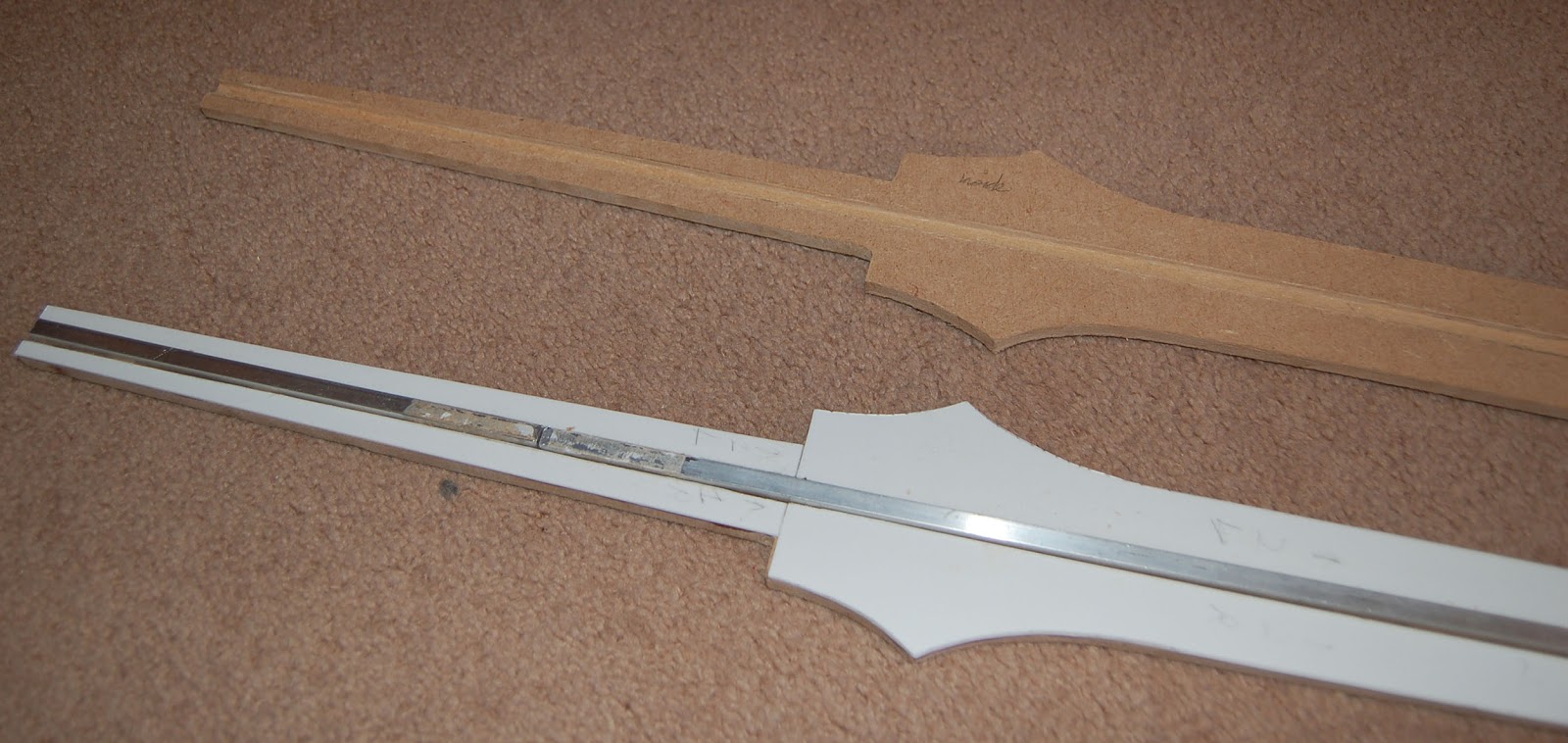
I drew the centre line onto the
sword blanks, then shaped them using a rough sanding drum on my Dremel and low
grit sandpaper on the palm sander, using the centre sheet of styrene as a guide
while grinding the edge. Once I had marked out the fullers on each blade, I
used narrow radius sanding drums and sandpaper wrapped around a wooden dowel to
hollow out the channels. After all this sanding, the MDF was getting knobbly
and hard to work with, so I brushed on a layer of Smooth-Cast 300 resin to give
me a better surface for sanding and finishing.

With the basic shape of the
blades complete, I decided to make the scabbard next so that I could align the
blades and ensure their cross guards would fit correctly when the swords were
sheathed. My initial plan was to shape a half scabbard from MDF and mold and
cast it, but I quickly realised that this would not be feasible with the tight
tolerances I was working within. I always try to use each project as an
opportunity to learn new skills, so I considered a variety of solutions for the
scabbard material: vacuformed styrene, heat-formed thermoplastic, fibreglass. I
had previously used fibreglass for making matrix molds, so I did some research
into similar materials, and settled on carbon fibre as my material. It fit all
my criteria: thin enough to use within tight tolerances, and strong enough to
retain rigidity over the long, thin length of the scabbard, while also
protecting the blades within, and cleaner to work with than fibreglass.
Once I had decided on my
material, I started work on the scabbard by shaping a buck out of MDF over
which to form the carbon fibre. I cut a second sheet of MDF with the same
outline as the scabbard half and pinned it to the back of the buck, so that I
could allow excess carbon fibre to overhang when I was stretching it over the
buck. The buck and this baseplate were sanded, primed and sealed, then covered
in release agent to prepare it for the carbon fibre layup.

A coat of epoxy was painted onto
the buck and allowed to start curing before laying down the initial layer of
carbon fibre. Two additional layers were added, with a coat of epoxy painted on
between each. I clamped tongue
depressors along the edges of the baseplate to stretch the material and
pull it evenly over the buck. Once the epoxy was cured, I was able to separate
the buck from the baseplate, then run the Dremel with a cutting disk along the
back of it to remove the excess material and get a consistent line for the half
scabbard. Unfortunately, I had some problems with releasing the carbon fibre
from the buck, and after trying varnish, polyurethane and epoxy to seal the
buck, and using a variety of release agents, small parts of the buck were still
tearing off each time. I didn’t mind sanding the excess material off the carbon
fibre, as the pieces were structural and wouldn’t be visible in the final prop,
but the damage to the buck required patching with Bondo, sanding, priming and
sealing each time.

Once I had completed the two
halves for each scabbard, I lined them with various thicknesses of foam and
foam tape so that each one would cushion their corresponding blade. The halves
were then clamped together and prepared for a final carbon fibre layup along
the join. I first sealed the join with aluminium tape to prevent any epoxy
dripping through and soaking into the foam, then coated it with epoxy and laid
a thin strip of carbon fibre along the rounded edge of the scabbard. After
applying two or three layers, the carbon fibre was lifting due to the curve of
the shape I was trying it adhere it to. I grabbed a roll of plastic sheeting
and stretched it over the scabbard, holding the carbon fibre in place, and thankfully
was easy to remove once the epoxy had cured.

With the major parts of the props
complete, I focused my attention on sculpting and fabricating all of the
smaller pieces, including guards, pommels and scabbard hardware. I
unfortunately don’t have any work in progress photos for these parts, but the
general approach was to cut the profile out of styrene, then bulk it out with
either MDF or Apoxie sculpt and sand it to the final shape. This method was
used for the blocks and arms of the guards, and for the fluted grip. To create
the chape and locket of the scabbard, I covered the top and bottom of the
scabbard in painters tape, and sculpted over it with Apoxie Sculpt.
I used different sculpting
techniques for each of the pommels. The bottom of an empty spray can was used
as the base for the rounded concave shape of the Steel sword’s pommel. The can
was held upside-down with the nozzle clamped down to drain the propellant, a
hole was drilled to pour out any remaining liquid, then the base was cut out
using a steel cutting disc on the Dremel. I cut and glued thin layers of
styrene into the concave piece to define the basic shape of the wolf head. The
details were then sculpted over this using a blend (about 60/40) of Games
Workshop’s Green Stuff and Milliput Superfine White epoxy putties that I find
useful for sculpting miniatures and smaller parts.

Many of the swords’ pieces were
either symmetrical or required two identical copies to make the finished piece.
For symmetrical pieces, including the locket and the central ring part of the
grip, I only sculpted half the shape, then created quick temporary molds to
mirror the piece. Two casts were pulled from each mold, the halves glued
together, and the gaps filled to form the final master. A similar approach was
taken for the pommels, with one wolf head of each style being sculpted, molded
and cast twice, with additional sculpting and fabrication to incorporate the
castings into the finished pommel master.
Once I had all of the hardware
finished, I checked the fit of all the pieces, filling gaps and ensuring that
everything was correctly aligned when the guard and pommel were attached to the
tang and the blade placed in the scabbard. I did a final pass on the blades to
finish the outline and sharpen up the centreline, then every piece went through
the prime, sand, repeat process until I was happy with the quality. Every part
was sanded up to 600 grit and given a final layer of black acrylic spray paint.
In order to make the blades look as realistic as possible, I wanted to cold cast
every piece, which meant starting by making lots of molds.

I stocked up on Smooth-On’s Mold
Max 40 and clayed up the hardware pieces. These were mostly straightforward
two-part box molds, though the scabbard hardware was slightly more complicated
as the scabbard needed to fit fully through the locket and partially through
the chape. The locket (above, bottom left image) had separate internal and
external mold lines defined in clay, so that one half of the mold captured the
exterior detail, while the other half became a plug to define the scabbard’s
shape.
Continued in: Part 2
Superior Wolf School Swords and Harness, The Witcher 3 (Part 2)
Creating the molds for the blades
was a much more complicated and involved process. Due to the size of the
pieces, I decided to make matrix molds with a fibreglass shell. Luckily, both
blades are roughly the same shape, so I only needed to create a single shell
within which I could pour both molds. I started by laying one of the blades on
MDF and claying up the shape of the first shell half around it, including
registration for the mold and for the second half of the shell, and pour holes
for the rubber. This was sealed and painted with a coat of epoxy, before laying
layers of fibreglass and more epoxy coats. When the fibreglass was cured, I
removed the clay, flipped it over, sculpted the second half of the shell, then
sealed it and applied release agent, and laid down the second half of the
fibreglass. I embedded a steel pole into each half of the shell to improve its
strength, and once the second half was cured, I cleaned up the excess
fibreglass, drilled in holes to bolt the halves together, and added smaller
holes to allow air bubbles escape during the molding process.

Unfortunately, fibreglass doesn’t
like sharp angles, and when I removed the clay from the finished shell, I
discovered that there were a lot of voids and lifted fibreglass on the inside.
This added a lot of work time as I had to sand down the fibreglass and fill it
with Bondo to redefine the internal shape of the shell. When this was complete,
I primed and varnished the interior to make sure there was no bubbles or
surfaces for the rubber to get stuck in to.

With the fibreglass jacket
complete, I clayed up the first blade and bolted the jacket together. I mixed a
large bucket (nearly 4kg) of Mold Max 40 and began slowly pouring this into the
shell. As the silicone filled the shell, it pushed air bubbles out through the
holes I had drilled, which I patched with clay once silicone started leaking
through. The rubber was left to cure, then the jacket flipped, opened, the clay
removed, release agent applied, jacket re-sealed and the second half of the
silicone mixed and poured. Once the mold for the first blade was finished, it
could be safely removed from the jacket, and the second mold made following the
same approach.
After finishing all fourteen
molds, including the two huge blade molds, it was time to start casting. The
casting for the two-part block molds was relatively straightforward, though I
did have some curing issues while testing the slower-curing Smooth Cast 305, so
I stuck with Smooth Cast 300 for the final pieces. Each mold was dusted with
aluminium powder and sealed, part A and part B of the resin was measured out,
with a drop of black dye and some additional aluminium powder added to part B
(about 50% powder to part B, by weight). I usually mixed enough to pour into
two or three of the smaller molds as a time, rotating the molds and tapping
them gently to release air bubbles as I poured. It took some time to learn the
intricacies of each of the molds, and since I was going for a cold cast finish
I couldn’t have any bubbles or imperfections, so it took a few attempts to get
a set of castings that I was happy with.
As with the molds themselves, the
casting of the blades was a much more difficult process. I knew that I would
need to embed a steel rod into the casting to give each blade strength, and
that I was working with a 1-2mm tolerance between the rod and the surface of
the blade. For my first attempt, I dusted the mold with aluminium powder,
sealed the jacket around it and secured it upright, lowering the rod in through
the pour spout. I mixed and poured a full batch of Smooth Cast 300 (about 600
grams of plastic), only for most of it to leak out onto the floor due to the
pressure exerted by the liquid on the narrow mold. Additionally, when I removed
the cured plastic from inside the mold, the steel rod was sticking through the
surface.

The solution to embedding the rod
was to start the casting with an open mold. The mold was dusted and the rod
carefully suspended over one half of it using thread. The rod was placed close
enough to the mold wall so that it wouldn’t rest against either side, but also
with enough space to allow the resin flow freely around it. This step was a
separate challenge for both blades, as each have a different layout of fullers
and centreline that have to be avoided. With the rod in place, half of the
resin was poured into the open mold, getting it as close to the edge of the
mold as possible while not overflowing. With the rod successfully embedded, it
took me a handful of failed attempts before I had a reliable technique for
producing high-quality finished castings.
In order to minimise leaking of
the resin, I initially attempted doing multiple partial pours into the closed
mold once I had completed the open pour to secure the rod. I experimented with
quantities and pouring techniques, eventually resolving the leaking. However, I
now had streaks and curing inhibition between the separate pours, and each
attempt was taking hours, with a lot of wasted resin on every failure. I
figured that I could use the initial closed mold pour to coat the surface of
the mold, and once it had cured backfill it with additional pours until it was
solid.

To produce the final blade
castings, I first secured the rod using my open mold technique, then closed the
mold and bolted the jacket together. Next, I mixed up a small quantity of
Smooth Cast 300 (about 80 grams part A) and poured this into the mold so that
it flowed along the steel rod instead of streaking the aluminium powder off the
mold surface. As soon as this resin was poured, I quickly and carefully slushed
it around the mold so that it completely coated the surface, again taking care
not to wash away the aluminium powder. This step required lifting and rolling a
four and a half foot long fibreglass monstrosity which held nearly 10Kg of
rubber inside it. Once the surface layer was cured, two additional batches of
resin were poured to backfill the piece, again using small quantities so that
the surface layer wouldn’t deform under the pressure of the liquid.

Getting away from the dust and
mess of fabrication and casting, I began work on the leather covers for the
scabbards. Starting with a veg-tanned cow side, I cut a rectangle of leather
for each scabbard, long enough to fit into the scabbard’s chape and locket.
This leather was wetted and stretched over the scabbard, clamped in place along
its centreline. Once it had dried, most of the excess was trimmed away and I
laid in the pattern. I cut a hexagonal template in styrene and marked in the
centre points of each of the partial circles and the larger circle that
surrounds them. I set the template on the dampened leather, then placed my wing
divider in each of the centres and scribed the circles, avoiding marking the
centre point holes on the leather. The scabbard narrows from top to bottom, so
the pattern got smaller, requiring me to reduce the radii and make increasingly
smaller styrene templates. Once the pattern was marked onto the leather, I
hammered in all of the stitching holes using a mallet and stitching stamp.

The leather was dyed with Angelus
Leather Dye’s Brick dye, buffed and sealed. Next began the time-consuming
process of saddle-stitching the pattern for both scabbards. For each part of
the pattern (i.e the outer circle and inner flower-like design), two needles
were tied to the ends of a piece of thread, and the part was hand-stitched:
stitch inner pattern, remove needles, rethread needles, stitch outer pattern.
Rinse and repeat for 32 flowers per scabbard! Luckily as the pattern got
smaller, the time required to stitch it went down. With the pattern complete,
the leather was stitched onto the scabbard. Its edges were trimmed down close
to the stitch line, dyed and burnished.

At this point, all of the pieces
of the swords were fabricated and ready for finishing and assembly. All of the
cold cast parts were cleaned up to remove any mold lines, then buffed with fine
steel wool and polished with Autosol Metal Polish. The inner surfaces of the
locket and chape were hollowed out slightly to allow them fit over the leather
when attached to the scabbard. I used 5-minute epoxy to glue the pieces of the
guards together and attach them to the tang. For the grip, I dyed veg-tanned
leather cord the appropriate colour (Brick for the Silver Sword, Chocolate for
the Steel Sword), and wound it around the grip, securing it in place with
leather glue. With the swords assembled, I added some subtle weathering,
focussing on the pommels and the base of the blade. I used a black ochre powder
as a close approximation of dirt and grime, mixing it with water and painting
it into the corners and crevices, then wiping most of it off.

Part of the iconic design of
Geralt and the witchers is the pair of swords hanging across their back, hilts
sticking over their shoulder. With the swords and scabbards complete, I felt I
couldn’t leave the project without attempting to create a harness to achieve
this look. While The Witcher 3 does a great job of rendering highly-detailed
weapons and armour, it takes some slight liberties with how the swords are hung
from Geralt’s back. Most armours in the game are designed with straps and parts
to represent the sword harness, but the exact method of mounting the scabbards
is not present. With this in mind, I picked my favourite armour design and spent
some time figuring out if I could make it work practically to hang the swords
over my shoulder.

As with the swords, my favourite
armour in the game is the Superior Wolf School set, which has a set of studded shoulder
pads and straps worn over the jacket. The shoulder pieces are strapped together
across the chest, and have buckled under-arm straps, so the piece can be
fabricated and worn separate from the armour. I knew that I’d need two mounting
points on this to hang the swords across rather than straight down, and after
careful study of the in-game reference, I had a fair idea where these mounting
points would be.
I started by drawing out the
pattern on cardstock. I did the shoulder pads first, using my scabbards and the
metal rivets as scale reference. I drew the straps longer than necessary, then
cut out the card and taped it together, resizing it until I was happy that the
piece correctly fit my shoulders. Next, I transferred the pattern onto some
heavy veg tanned leather, cut it out, and punched in the stitching holes. I
temporarily stitched the pieces together and did a test fitting, ensuring that
it sat correctly and everything lined up.
At this point, my leather matched
the in-game design, but it was missing a way to mount the swords. I cut out two
pairs of leather straps and attached buckles to them, sizing them to fit around
the top of the scabbards. I tied the straps onto one of the scabbards, and a
friend wore the work-in-progress harness while I held the scabbard up to it and
marked in where the straps would attach. I stitched on the straps for the first
sword, then lay the second scabbard side-by-side to mark its mounting points. The
top straps for both swords anchored to one of the shoulder pads, and were
stitched together for additional support. For the second scabbard, its lower
strap didn’t actually come in to contact with the main harness, so I ended up
stitching it to the strap for the first scabbard, and ensuring that this strap
was stitched securely enough to the cross-strap of the harness to support both
swords.

Confident that the piece fit
together and that the swords hung from it correctly, I removed the temporary
stitching, labelling each piece so I would know how everything went together
once it had been dyed and finished. I punched in the holes for the rivets, and
the stitching holes for all the decorative stitching, as well as cutting out
strips of thin veg-tanned lambskin to stitch onto the edges of the shoulder pads.

My standard practice for
finishing leather is: dye the pieces and let them dry, buff them with a cloth
to remove the excess dye, rub olive oil into the grain side and let it dry,
brush gum tragacanth onto the edges and flesh side and burnish, and finally
seal the grain side with leather finish. For the harness, all of the pieces
were dyed with Coffee Angelus Leather Dye.
With the leather pieces finished,
I set the rivets and began stitching, taking care with my order of operations.
The decorative stitching for the buckled under-arm straps was completed before
stitching in the buckles, then the cross-chest straps were stitched before
mounting the under-arm straps to them. The edges of the shoulder pads were
wrapped with thin lambskin, which was doubled-over and stitched above and below
the leather of each pad. Where the shoulder pad meets the cross-strap, I
stitched through four layers of leather – the two sides of the lambskin edging,
the shoulder pad, and the cross-strap. Once the main harness was complete, the
mounting straps were stitched into place and the swords were ready to be
attached.
Thanks for reading,
Terry
Subscribe to:
Posts
(
Atom
)